In my last post, I detailed the hardware for making the poor man's ballistic chronometer. That post can be seen here: http://inkarlslab.blogspot.com/2012/01/poor-mans-ballistic-chronometer-part-1.html
Today I show how to use it.
Before I go farther, I should remind folks to wear appropriate eye protection when shooting any weapons and to make sure no people or animals are anywhere near the target or behind the firing range. This seems like common sense, but in this age I'd better say it anyway.
With that matter handled ...
As was explained in the first part, the poor man's chronometer works with a computer's sound card to capture the instant the dart leaves the muzzle and the instant it hits the target. Using a sound editing program such as Audacity, one can measure the interval between these two events. Audacity is quite versatile, is free, and is available for both Windows and LINUX computers. There is some support for certain Mac OSes, too. Since it is free and readily available for most people, and I've used it for nearly 10 years on LINUX systems, Audacity is what I'll detail here. If you have something else, feel free to use it - the basic idea is the same.
First, A Word About Sound Cards
Nearly every computer sound card has a microphone level input. Microphones tend to provide a signal of just a few millivolts. The same is true of the modem speaker - 'noisemaker' - that I used for my target strike microphone sensor. Some sound cards are also furnished with a line level input. "Line level" is generally a few hundred millivolts - 300 being quite common.
If you build my circuit and have a sound card that accepts line level inputs, by all means use that. You'll want to delete the resistive attenuator on the output of the OP amp - just keep the coupling capacitor and hook it up directly.
Because my particular sound card ONLY has a mic level input, I used the attenuator in the output of my circuit shown in the previous post. If you are using a mic level input, these resistor values should get you somewhere "in the ballpark".
Microphone Inputs on sound cards often use a "stereo" 3.5 mm (1/8") plug. The reason for this is many computer microphones get their power from the computer itself, and so either the 'tip' or 'ring' contact is used for power - generally anywhere from +5 to +9 volts, and the other remaining contact is for the audio. You need to do an Internet search on your particular hardware and see how yours is wired. Failing that, here's what I did:
With Audacity or other sound recorder app open and 'recording', connect a stereo 3.5 mm 'patch cable' to the mic input and touch the tip, then the ring, contacts with a screwdriver to see which one gives the tell-tale 60 Hz hum and/or clicks. They BOTH may, but the one you want will be much louder. (Yes, this technique is a bit "ghetto", but it's quick and works.) Connect the output of the circuit I described in "Part 1" to this contact and the ground sleeve.
Data Acquisition Using Audacity
Audacity can be downloaded from Sourceforge, or if you have LINUX, you can use your distribution's package manager to grab it and install it.
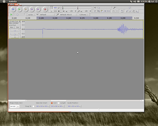
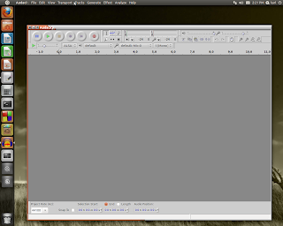
Once you have Audacity installed, open it and you will see something like the photo below:

The menus will allow you to choose sampling rates, which sound card input to use, ...
Using the "Edit" menu, select "preferences". Under "preferences", select 'devices'. You should check to see that under "record" your device is shown. It will likely default to something like "Default: Mic:0". If you are using the line input, click on that box to change it to "Default: Line:0". Also make sure "mono" is selected - since you will not be making a stereo recording.
Now, select "Quality" in the left-hand menu bar. The sampling rate should be set to 44,100 Hz and the Default Sample Format should be set to "32-bit float".
Click "OK" to close that menu.
The Procedure"
1) Put the optocoupler on the muzzle of your blowgun, air pistol, whatever you're shooting.
2) Attach the microphone to the edge of the target - this can be done with duct tape as I did, or by whatever means you find suitable.
3) Make sure the muzzle sensor photo transistor and LED, microphone, power are all connected to the board described in my last post.
4) Start the 'record' mode in Audacity. You should see an oscilloscope-like trace being drawn. thumping the target or sticking your finger in the optocoupler should cause a visible trace, indicating everything is working. You may need to adjust the slide control for the microphone gain to get the waveform display you need. You do NOT want the waveform to be severely 'clipped' - that will potentially cause errors in your measurements.
5) Measure out your shooting distance from the target to the blowgun muzzle. In my test case shown here, I used 7 feet. I actually stood 12 feet away, so the MUZZLE of my 5-foot blowgun was at 7 feet from the target.
6) Shoot the blowgun. You should immediately see what appears to be two pulses close together on the graphical waveform in Audacity. Press the 'stop' button.
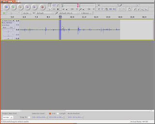
See the photo below - your waveform will look something like this. The part highlighted in grey is the blowdart firing; the other peaks in the trace are noise from the mic wiring being jiggled.

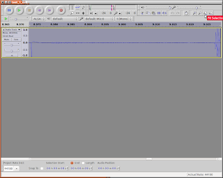
7) Using the cursor, highlight just the double pulse part of the waveform. Refer again to the above photo. Press the icon that looks like a magnifying glass with the -<-->- symbol below it. This will expand the part you highlighted to fill the whole window. See picture below.

8) Look at the time track above the waveform trace: You will see timing to 1000ths of a second. Note the times the optocoupler pulse and the target "thud" start. Write these numbers down, or enter them into a spreadsheet.
9) Subtract the two numbers you got in step 8 and write that figure down. This is your time of flight. In the photo, note that the optocoupler triggered at about 8.973 seconds and the target "thump" started at about 9.027 seconds. This gives a time of flight of 0.054 seconds.
10) Simply divide the shooting distance you measured in step 5 by the number you calculated in
step 9. This result is your average velocity. Note from the example the average velocity during it's flight of 7 feet is approximately (7/.054), or 129.6 feet/second.
The average velocity is the average velocity over the whole trip from the muzzle to the target. This number "absorbs" any deceleration during the flight as well as the instantaneous muzzle velocity leaving the weapon.
To get a good approximation of the muzzle velocity, simply get close to your target. With a blowgun, a distance of 2-3 feet from the target should give a reasonable figure. If you are clocking a more powerful weapon such as an air rifle, you can (AND FOR SAFETY REASONS SHOULD) get a bit farther away from the target. Some experimentation will be in order here.
Below are a couple "action shots" of the completed unit. Sorry about the blurry picture of the target - trying to hold the camera AND the blowgun steady was a challenge ;) Note the sensor LED glowing at the blowgun muzzle.


Going Farther
While this is likely NOT the most accurate method of clocking these projectiles, it's pretty good. It's certainly good enough for what I need it to do. Basically I want to see how lengthening or shortening the tube, or changing its diameter, affects my blowgun's performance. I also wanted to experiment with different ways of making darts.
Archery: For this, I would do away with the optocoupler and simply put another mic on the bow itself - near the handle. I would measure the time from the bowstring "twang!" to the target "thump!" as the arrow hit. The rest I would do as described above. This would be an excellent way to compare my home made PVC bows to wooden or factory made ones. Simply shoot the same arrows at the same distance from the different bows and clock the speeds.
Firearms: One could do as I have done here, or simply use ONE mic with NO optocoupler and shoot at a target that would make a distinctive "clank" that would be audible in the recording. Measure that interval between the gun firing and the "clank", then subtract the time the sound took to travel the distances between gun and mic and target and mic. Divide the distance from the time calculated herein and you will have a pretty good idea of how fast your bullet was moving (on average). This technique is discussed on numerous web sites.
Crunching the data:
One can collect data from a number of firings on one recording. These can be plotted on a graph using any spreadsheet program. If you want to get fancy, calculate averages and standard deviations during your tests. Calculating standard deviations for your test runs will give you a good handle on how consistent your performance is. To aid in record-keeping you could even title your recordings something like "nail_7ft_01072012" - for "nail dart", 7 ft distance, and the date. Or "48_nail_7ft_01072012" could mean 48" blowgun, "nail dart", 7ft distance, January 07, 2012.
This would also be an excellent physics lab project for college students.


No comments:
Post a Comment
Constructive comments are welcome! Spam, or any abusive or profane comments will be deleted.